


In every flow system of fluid, there is a need to estimate the rate of flow. There are instances that the liquid has high heat capacity, and thus it needs a coolant flow meter. The idea is to let the fluid flow as you regulate the heat. The system uses a principle of thermal mass flow. The only addition is the principle of conservation of energy. These sensors are not affected by the properties of the flowing fluid. The pressure, temperature, do, and density of the fluid do not affect the flow rate measurement. These meters work differently from the volumetric meters. You do not need any calculations to get the flow rate. This factor has made the thermal mass flow meters gain popularity within a short time.
Coolant flow meters are highly applicable where there are engines and motors involved. They are used to monitor the engine and motor performance.
Thermal Mass Flow for Gases (Bypass Design)
When a thermal mass flow meter is mentioned, many people visualize a bypass sensor. It is one of the many thermal sensors in the fluid flow industry. With the bypass principle, some part of the fluid- mostly gasses- is diverted into a small capillary—the capillary acts as the sensor. There are two heating points (point A and point B). Both points are subjected to the same heat. Then the temperature of the fluid is taken at both ends. The difference is the flow rate of the fluid through the channel.
In the bypass principle, when the flow rate is low, the heat difference is high. The difference decreases as you increase the flow rate. The reason behind this is that a fluid at slow velocity will have enough time to heat up. But with speed, it has short contact time, thus insufficient time to heat up. These types of meters are applicable in channels with corrosive gases.
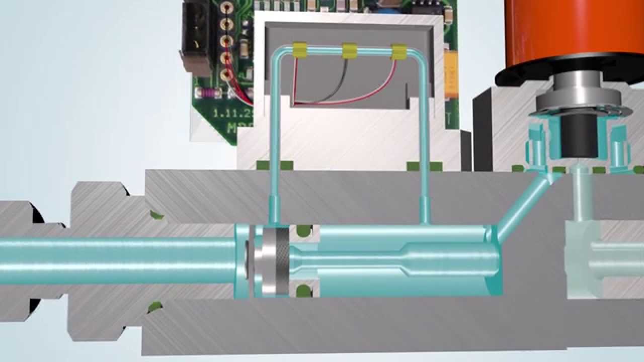
Heated Tube Design

The design has some similarities in the working principle as the bypass design. The difference is that there is no bypass channel for this kind of a meter. The heater and the sensor are attached to the external surface of the pipe. This design is used in liquids and gases. It is effective when using corrosive fluids. The sensor is placed far from the heater. This is because the temperature of the walls and the fluid is similar farther from the heater.
There are two operating modes in this system. In the first mode, you keep the power input constant and observe the rise in temperatures. In the other mode, you keep the difference in temperature contact. You then observe the amount of power needed to maintain the temperature. When you need a coolant flow meter, you use a cooling sensor on a pipe carrying hot fluids. The rest of the principles operate the same.
Air Velocity Probes
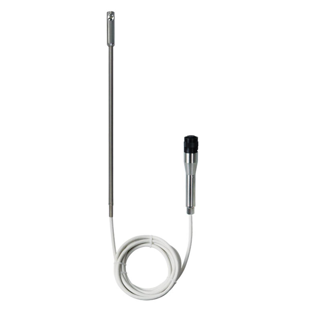
This design is a bit complex. Maybe that explains why they are not popular. They are mainly used to measure the flow rate of gasses. The system is not affected by dust particles within the gas. The first sensor should raise the heat of the fluid to 60 degrees Fahrenheit. It then maintains the heat that reaches the second sensor. As the flow rate increases, the power input at the first sensor should increase.
The design uses a principle of heat difference at two points. The heater and the sensor are inserted on the tube's interior, unlike the other two above.
Hot Wire Anemometer

This principle is applicable in the intrusive kind of thermal sensor. It is mainly used in gas mass flow measurement to reduce the coating of the sensor. The sensor wire is heated. As the gas passes past it, the wire cools down. The rate at which it cools down related to the flow rate.
Conclusion
The coolant flow meter is important in engines and motors. Thus, you should understand all the principles and fluid properties. It advises on the flow meter to select.


Thousand years ago, people knew the theory of flow meters and their analysis when agriculture, flooding, and water conservation became vital to humans.
The uses of liquid flow meters primarily hold in industries like pharmaceuticals, metallurgy, petrochemicals, home energy, pulp & home.
Day by day, the evolution of meters and their use has evolved, but their need endures the same as skill.
Some kinds of meters primarily focus on fluids and gases in a pipe.
The main perks of these meters are improving the accuracy, resolution, and precision of the liquid.The working law of the liquid flow meter is to gauge the amount of gas and fluid that otherwise streams around the device.
These tools work with the same end aim but in various ways.


Subsea Multiphase Flowmeter Market report published by Value Market Research, which studies the future outlook of the market.
It includes the size, share, growth, trends, key players, segments and regional analysis in detail during the study year 2020-2027.The research report also covers the comprehensive profiles of the key players in the market and an in-depth view of the competitive landscape worldwide.
The major players in the subsea multiphase flowmeter market include Weatherford, Baker Hughes, AMETEK Inc., Schlumberger Limited, ABB Ltd, TechnipFMC plc, Emerson, KROHNE Japan KK, Peitro Fiorentini S.p.a., Haimo Technologies Group Corp and others.
This section consists of a holistic view of the competitive landscape that includes various strategic developments such as key mergers & acquisitions, future capacities, partnerships, financial overviews, collaborations, new product developments, new product launches, and other developments.Get more information on "Global Subsea Multiphase Flowmeter Market Research Report" by requesting FREE Sample Copy at https://www.valuemarketresearch.com/contact/subsea-multiphase-flowmeter-market/download-sampleMarket DynamicsThe growth-inducing factor for the market has come from the many advantages they offer to end-users in offshore oil and gas operations.
Swiftly aging maturing oil wells in the offshore environment is a key trend driving the growth of the market.
However, the high capital expenditure required for deployment may restrict the growth of the market over the forecast period.The research report covers Porter’s Five Forces Model, Market Attractiveness Analysis, and Value Chain analysis.

Digital Flowmeter Market research report includes specific segments by region (country), by manufacturers, by Type and by Application.
Each type provides information about the production during the forecast period of 2016 to 2027. by Application segment also provides consumption during the forecast period of 2016 to 2027.
Understanding the segments helps in identifying the importance of different factors that aid the market growth.Download FREE Sample of this Report @ https://www.grandresearchstore.com/report-sample/global-digital-flowmeter-2021-704Segment by TypeField MountingPanel MountingSegment by ApplicationOil & GasChemicalOtherBy CompanyOMEGA EngineeringNUCLUS CONTROLGPI MetersDwyer InstrumentsAssured AutomationGreat Plains IndustriesKOBOLDMaster MeterElsterNeptuneProduction by RegionNorth AmericaEuropeChinaJapanConsumption by RegionNorth AmericaU.S.CanadaEuropeGermanyFranceU.K.ItalyRussiaAsia-PacificChinaJapanSouth KoreaIndiaAustraliaTaiwanIndonesiaThailandMalaysiaPhilippinesVietnamLatin AmericaMexicoBrazilArgentinaMiddle East & AfricaTurkeySaudi ArabiaUAEGet the Complete Report & TOC @ https://www.grandresearchstore.com/manufacturing-and-construction/global-digital-flowmeter-2021-704Table of content1 Digital Flowmeter Market Overview1.1 Product Overview and Scope of Digital Flowmeter1.2 Digital Flowmeter Segment by Type1.2.1 Global Digital Flowmeter Market Size Growth Rate Analysis by Type 2021 VS 20271.2.2 Field Mounting1.2.3 Panel Mounting1.3 Digital Flowmeter Segment by Application1.3.1 Global Digital Flowmeter Consumption Comparison by Application: 2016 VS 2021 VS 20271.3.2 Oil & Gas1.3.3 Chemical1.3.4 Other1.4 Global Market Growth Prospects1.4.1 Global Digital Flowmeter Revenue Estimates and Forecasts (2016-2027)1.4.2 Global Digital Flowmeter Production Estimates and Forecasts (2016-2027)1.5 Global Digital Flowmeter Market by Region1.5.1 Global Digital Flowmeter Market Size Estimates and Forecasts by Region: 2016 VS 2021 VS 20271.5.2 North America Digital Flowmeter Estimates and Forecasts (2016-2027)1.5.3 Europe Digital Flowmeter Estimates and Forecasts (2016-2027)1.5.5 China Digital Flowmeter Estimates and Forecasts (2016-2027)1.5.5 Japan Digital Flowmeter Estimates and Forecasts (2016-2027)2 Market Competition by Manufacturers2.1 Global Digital Flowmeter Production Market Share by Manufacturers (2016-2021)2.2 Global Digital Flowmeter Revenue Market Share by Manufacturers (2016-2021)2.3 Digital Flowmeter Market Share by Company Type (Tier 1, Tier 2 and Tier 3)2.4 GlobalIf You Have Any Question Related To This Report Contact Us @ https://www.grandresearchstore.com/enquire-now/global-digital-flowmeter-2021-704CONTACT US:276 5th Avenue, New York, NY 10001, United StatesInternational: +1(646)-781-7170 / +91 8087042414Email: [email protected] Us On linkedin :- https://www.linkedin.com/company/grand-research-store


