


There are a few things to consider when choosing residual current sensors. First, check the maximum ampere-turns rating for the sensor. Second, make sure that the short circuit current rating is high enough. You can verify the maximum ampere-turns rating by reading the sensor's datasheet.
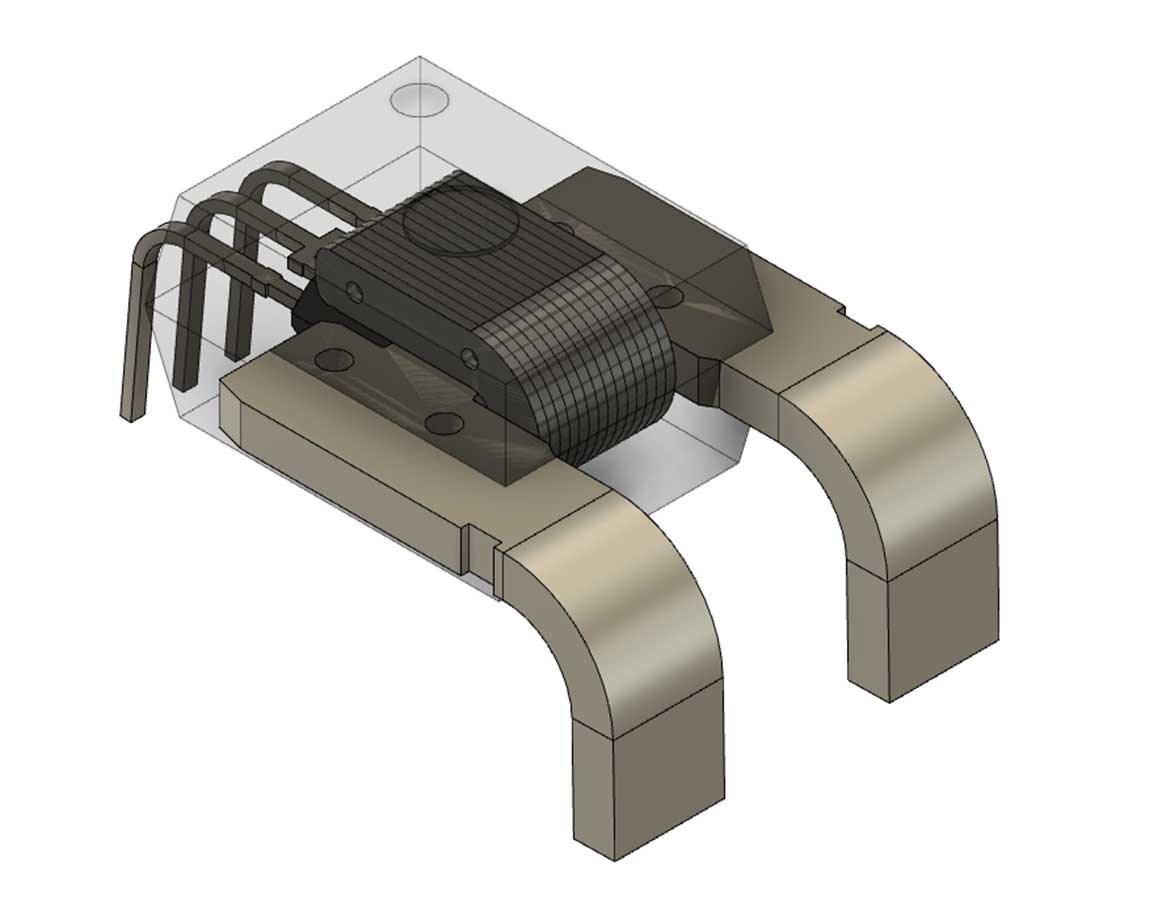
Magnetic Flux in The Core of The Current Sensor
The Residual Current Sensor (RCD) is an electromechanical device that measures unbalanced current. It is connected to the live and neutral conductors and must have a protective conductor (PE) outside the device. In case of an earth fault, an RCD will detect an unbalanced current by detecting a magnetic flux in its iron core. This flux produces a secondary voltage that flows through a relay. The relay consists of a permanent magnet, a coil, a spring, and a moving element.
To measure the residual flux, one must obtain the measurement method by comparing the leakage flux and residual flux. This is not an exact science; different measurement points result in different transfer functions, which affect measurement accuracy. Another technique is to measure the energy of a minor hysteresis loop, whose energy change depends on the direction of residual flux.
The magnetic flux in the core of residual current sensors is very important for power system protection equipment. It has an important role in detecting leakage currents in power systems. However, if the leakage current contains a DC component, the AC leakage current will be unable to be transferred to the secondary side of the current sensor. As a result, the protection performance will deteriorate or fail in a residual current circuit breaker.
Resistance of The Secondary Winding 4
Residual current sensors are devices that detect induced secondary voltage in the secondary winding of an A-type RCD. This voltage is used to test the tripping threshold of a residual current device. The induced voltage is proportional to the peak value of the residual current waveform.
The resistance of the secondary winding 4 for the residual current sensor depends on the primary and secondary currents. Hence, the resistance of the secondary winding 4 is determined by dividing the primary winding resistance by the secondary winding resistance. However, this approach is not enough, as the resistance of the secondary winding 4 is dependent on the DC component. This will result in a reduction in the protection performance of the residual current circuit breaker.

The secondary winding 4 has a first contact point 8 connected to the ground. An alternating-current measuring array 5 can be connected to the second contact point 9. By measuring the voltage difference in the secondary winding 4, the residual current can be detected. This is possible because the secondary winding can be fixed to a reference potential on one side.
Maximum Ampere-Turns Rating of The Sensor
The maximum ampere-turns rating of a residual current sensor is dependent on its current delay angle. In the laboratory, a 300-mA A-type RCD was tested to determine its residual current delay angle. The results are shown in Figure 20. This figure shows the relationship between the current delay angle and the peak value of the residual current.
Residual current sensors are available in two main types: F-type and B-type. The former is intended for waveforms like the A-type while the latter is intended for mixed-frequency residual currents up to 1000 Hz. The B-type sensor is designed to withstand low frequencies but has a higher ampere-turns rating.
The CT accuracy class is 0.2 for sinusoidal current at 50 Hz. This accuracy value decreases as the frequency increases, which is due to active power losses in the core and magnetization current.
Detection of The Unbalanced Current State in The Sensor
This paper presents a new technique for the detection of an unbalanced current state in residual-current sensors. In contrast to classical approaches based on parity equations and residual generation, the proposed method uses averaged machine-phase currents. Furthermore, it involves minimal tuning effort and is suitable for real-time implementation.

Residual-current devices are designed to detect and isolate unbalanced currents from electrical systems. They are wired in the power cord of an appliance and rated for a maximum current of thirteen amps but are designed to trip or latch when an unbalanced current exceeds 30 mA. This feature is especially useful for equipment which may be triggered by a sudden re-energisation of the power source. In the past, the sensitivity of residual-current devices was low and relied on finely balanced over-centre mechanisms.
In many applications, the residual current state can be derived from a ground fault in the distribution system. In this case, the fault current saturates the core of the CT. This can also cause a false opening of the detector. A CT should be matched with a relay with an appropriate ground fault detection range.


Global Automotive Electronics Sensors Market size was valued US$ 35.92 Bn.
Global Automotive Electronics Sensors MarketIncreased vehicle production globally, also rise in demand for an electric vehicle, implementation of strict government rules and regulations related to emissions, and increase in consumer demand for safety, comfort and luxury in vehicles, These are the factors driving the growth of global automotive electronics sensors market.Temperature sensing and control are among the most important and well-established functions in automotive electronics.
In automotive electronics, they are found especially in climate control and power-train applications.
Emerging, state-of-the-art, sensor technologies are defined here as those which are currently in the R stage of development, or those which have been newly introduced and which are expected to have a significant impact on automotive systems development.During the past two decades, market studies have continued to track the increasing deployment of sensors to automotive systems.
According to data from the Insurance Institute for Highway Safety, there are nine vehicle models -- including the Volvo XC90 -- in which no one in the United States died in the four years from 2009 to 2012, the most recent period for which data is available.Volvo still based in Sweden but now owned by China's Zhejiang Geely Holding Group (GELYY), wants to make this the case for its entire vehicle line up throughout the world.
That also helps Volvo predict how much safer its vehicles will be with each new advancement.Europe car industry has demonstrated signs of improvement in June 2020, boosted by the reopening of more showrooms.

Quite possibly the most significant parts of home support is pipe upkeep.
When the drainage system is damaged it is hard to do almost any of the house chores like cooking, cleaning etc.


